ESP8266
Introducción
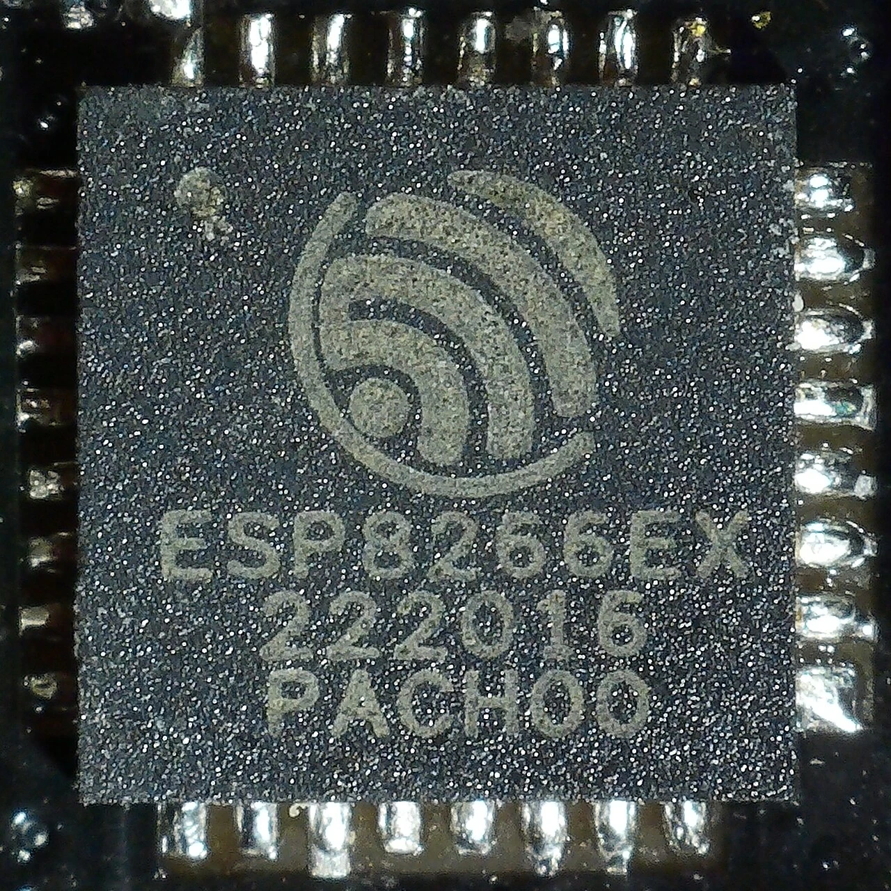
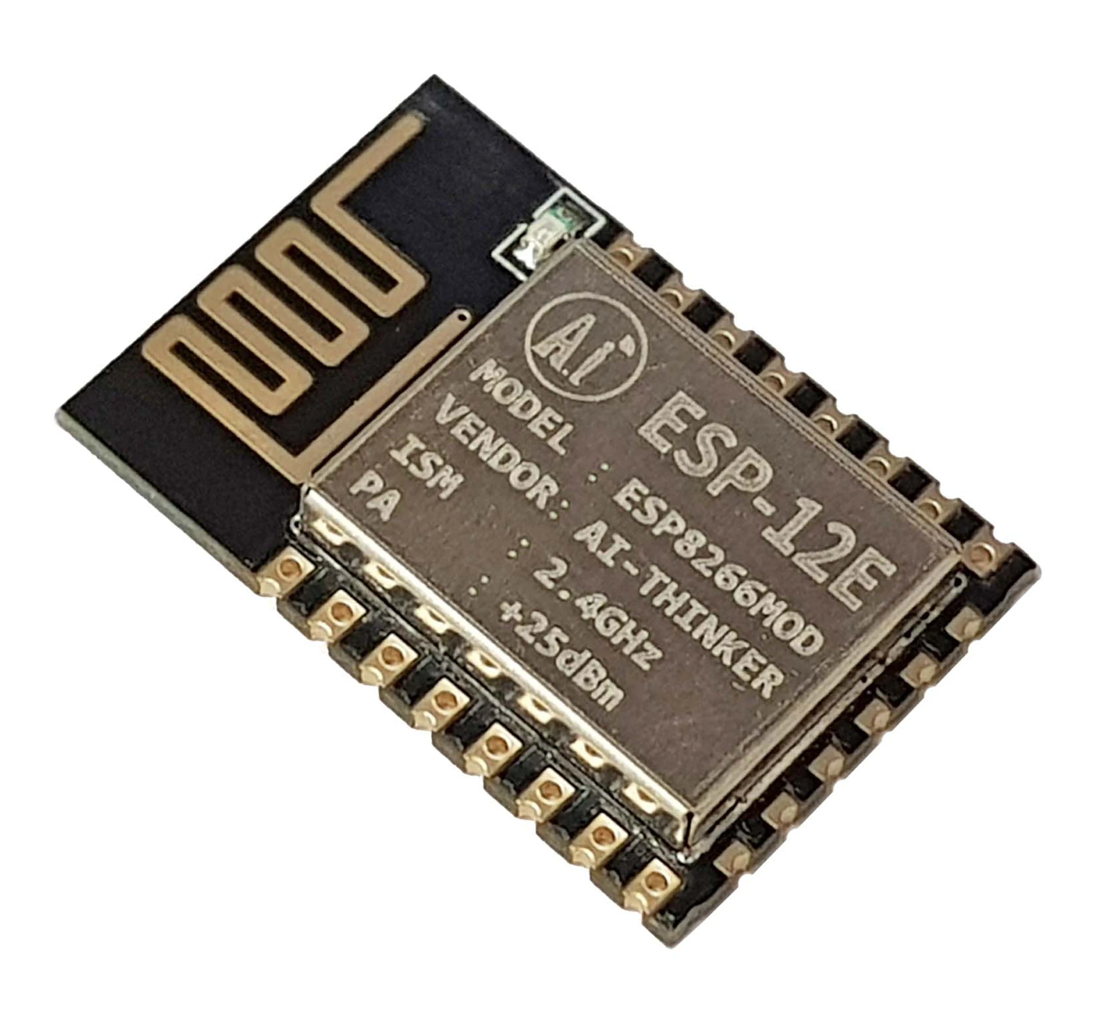
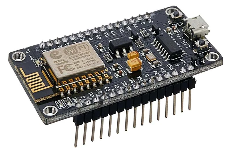
The ESP8266 is a low-cost Wi-Fi microchip, with built-in TCP/IP networking software, and microcontroller capability, produced by Espressif Systems in Shanghai, China.
The chip was popularized in the English-speaking maker community in August 2014 via the ESP-01 module, made by a third-party manufacturer Ai-Thinker. This small module allows microcontrollers to connect to a Wi-Fi network and make simple TCP/IP connections using Hayes-style commands.
However, at first, there was almost no English-language documentation on the chip and the commands it accepted. The very low price and the fact that there were very few external components on the module, which suggested that it could eventually be very inexpensive in volume, attracted many hackers to explore the module, the chip, and the software on it, as well as to translate the Chinese documentation.
These microcontroller chips have been succeeded by the ESP32 family of devices.
📖 from wikipedia
NodeMCU Specs
| ESP8266 | |
|---|---|
| Microcontroller | Tensilica 32-bit RISC CPU Xtensa LX106 |
| Operating Voltage | 3.3V |
| Input Voltage | 7-12V |
| Digital I/O Pins (DIO) | 16 |
| Analog Input Pins (ADC) | 1 |
| UARTs | 1 |
| SPIs | 1 |
| I2Cs | 1 |
| Flash Memory | 4 MB |
| SRAM | 64 KB |
| Clock Speed | 80 MHz |
| USB-TTL | based on CP2102 |
| WiFi antenna | PCB |
Pines
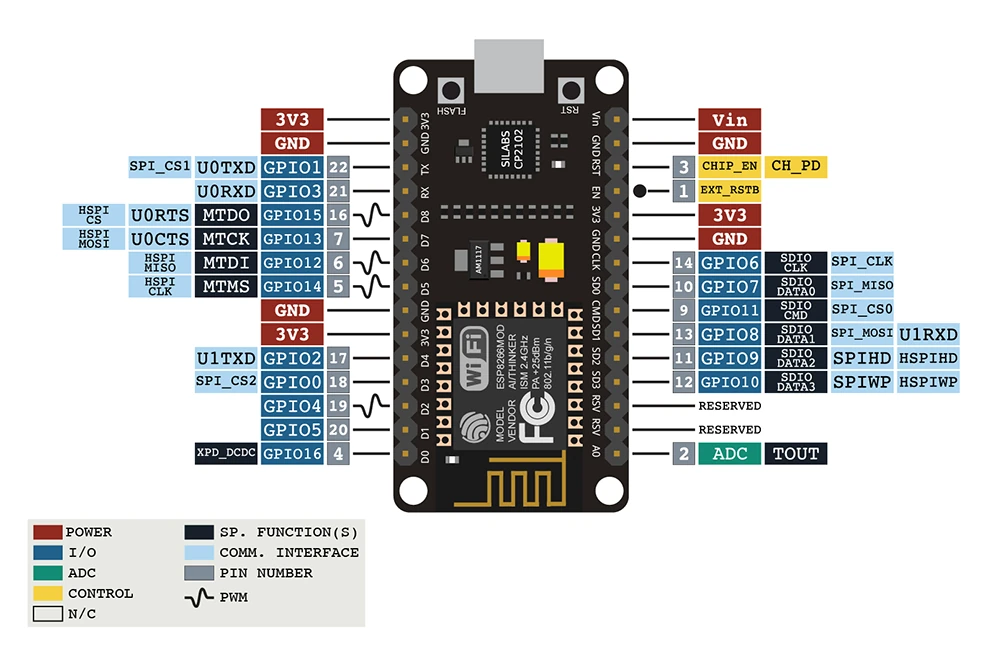
- El GPIO2 está conectado al led, y en el Arduino IDE lo podemos acceder a través de la constante BUILTIN_LED.
- El pin de RST (reset) está conectado al botón de RST y lo podemos usar para reiniciar la placa poniéndolo en estado LOW.
- Al poner el GPIO0 an LOW, la y reiniciar la placa, esta se pondrá en bootloader mode. Esto nos permite flashearla aún cuando, por alguna razón no entre en este modo automáticamente.
- Se puede generar una señal PWM (vía software) en todos los pinoes I/O con una resolución de 8 bits (0-255).
- El GPIO16 se puede utilizar para despertar al ESP822 de deep sleep mode, se debe conectar al pin RST.
- El bus I2C (implementación de software) normalmente utiliza los pines GPIO5:SCL y GPIO4:SDA
- El bus SPI (en el que está conectado el flash interno del módulo ESP12e) utiliza los siguientes pines: GPIO12:MISO, GPIO13:MOSI, GPIO14:SCLK, GPIO15:CS.
- El ESP8266 soporta la configuración de interrupts externos en todos los GPIO's menos en el GPIO16.
En la siguiente tabla los pines en verde son seguros de usar. Los que están en amarillo también pueden utilizarse, pero hay que tener cuidado porque a veces pueden formar parte de alguna función interna y comportarse de forma extraña, sobre todo en el boot. Los pines en rojo no se recomiendan para su uso como In/Out.
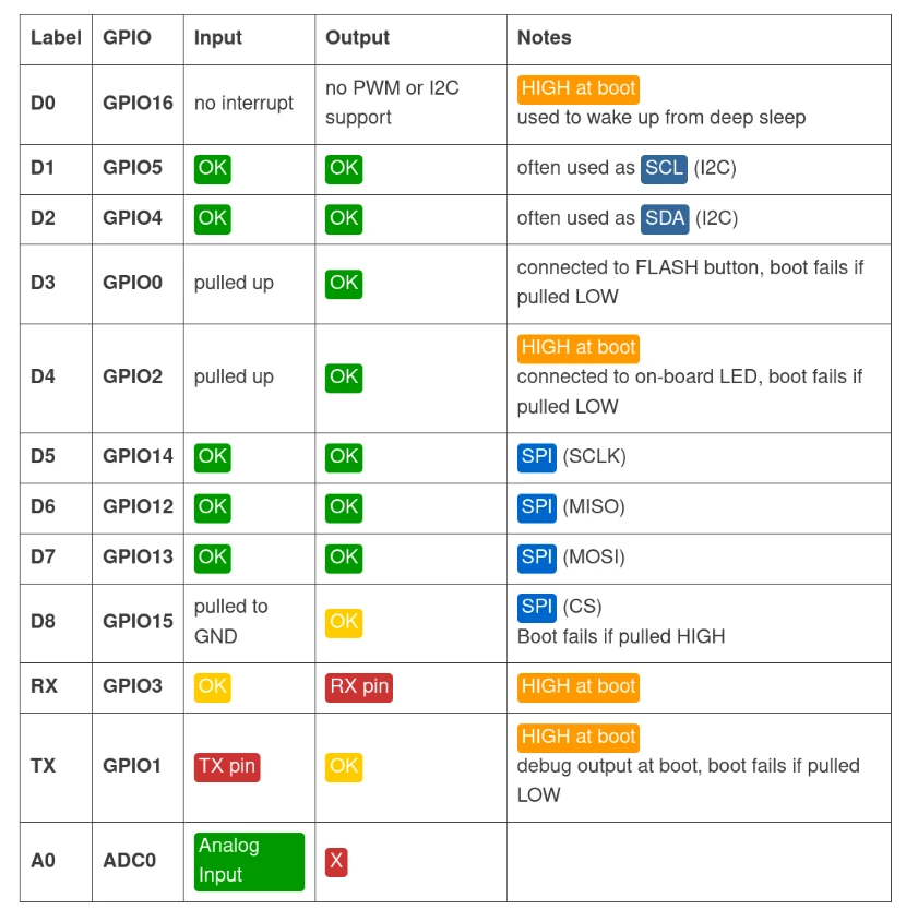
Los pines GPIO6 y GPIO11 normalmente están conectados al chip de flash, no se recomienda su uso por que pueden dificultar el proceso de boot.
Arduino IDE
Definición de placas (ESP8266)
Para poder programar la arquitectura esp8266 desde el Arduino IDE necesitamos instalar el core correspondiente.
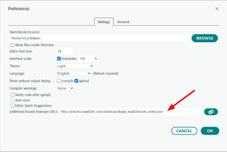
En la ventana de preferencias del Arduino IDE, en el campo Additional boards manager URLSs hay que poner el URL del repositorio donde se encuentra el software necesario.
https://arduino.esp8266.com/stable/package_esp8266com_index.json
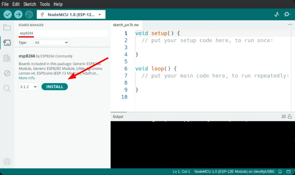
Después podemos instalar las definiciones abriendo la ventana Boards Manager (Tools → Board → Boards Manager...), allí buscamos el término _esp8266 y picamos el botón Install en las placas esp8266 by ESP8266 Community.
En algunas versiones de windows hemos encontrado que es necesario instalar un driver para poder comunicarnos correctamente con la placa. Antes de hacerlo asegúrate de que no puedes comunicarte con la placa siguiendo las instrucciones en la siguiente sección.
Si necesitas instalarlo, lo puedes bajar de la página de Silabs
Probando la placa
Una vez que la instalación haya concluido para estar seguro de que todo funciona correctamente podemos programar nuestra placa con el ejemplo Blink:
- Conectamos la placa con el cable USB a nuestro ordenador.
- Abrimos el código de ejemplo Blink (File → Examples → Basics → Blink)
- Seleccionamos la placa correcta: NodeMCU 1.0 y el puerto al que está conectada.
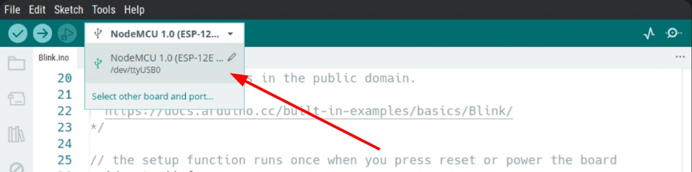
So ni sabes cuál es el nombre del puerto puedes revisar el menu antes de conectar la placa, y volverlo a abrir una vez conectada, el puerto que aparezca será el correcto.
- Por último hay que subir el código (Sketch → Upload ) o picar el botón de Upload (la flecha apuntando hacia la derecha.)
Si todo funciona correctamente deberíamos ver el led de la placa prendiéndose y apagándose cada segundo.
Si subir el código a la placa es muy lento en tu ordenador, prueba a cambiar la velocidad a 921600 en el menu Tools → Upload Speed
En ocasiones, por diferentes razones la placa, no logramos flashear la placa normalmente, para forzar bootloader mode manualmente hay que mantener picado el boon de FLASH y, sin soltarlo, picar brevemente el boton de RST.
Input/Output
Cualquier pin marcado como GPIO se pueden usar como input/output usando las funciones DigitalWrite() y DigitalRead().
DigitalWrite()
void setup() {
  pinMode(BUILTIN_LED, OUTPUT);     // Initialize the BUILTIN_LED pin as an output
}

// the loop function runs over and over again forever
void loop() {
  digitalWrite(BUILTIN_LED, LOW);   // Turn the LED on (Note that LOW is the voltage level
                                    // but actually the LED is on; this is because
                                    // it is acive low on the ESP-01)
  delay(1000);                      // Wait for a second
  digitalWrite(BUILTIN_LED, HIGH);  // Turn the LED off by making the voltage HIGH
  delay(2000);                      // Wait for two seconds (to demonstrate the active low LED)
}
DigitalRead()
// You can try a digital input with a push button connected to pin D4 (GPIO 2)
int pushButton = D4;

// the setup routine runs once when you press reset:
void setup() {
  // initialize serial communication at 9600 bits per second:
  Serial.begin(115200);
  // make the pushbutton's pin an input and activate the internal pullup resistor:
  pinMode(pushButton, INPUT_PULLUP);
}

// the loop routine runs over and over again forever:
void loop() {
  // read the input pin:
  int buttonState = digitalRead(pushButton);
  // print out the state of the button:
  Serial.println(buttonState);
  delay(1);        // delay in between reads for stability
}
AnalogRead()
En el ESP8266 solamente el pin marcado como A0 está conectado al ADC interno y se puede utilizar como input analógico, tiene una resolución de 10 bits que nos puede dar un valor entre 0 y 1023.
// the setup routine runs once when you press reset:
void setup() {
  // initialize serial communication at 115200 bits per second:
  Serial.begin(115200);
}

// the loop routine runs over and over again forever:
void loop() {
  // read the input on analog pin 0:
  int sensorValue = analogRead(A0);
  // print out the value you read:
  Serial.println(sensorValue);
  delay(1);        // delay in between reads for stability
}
AnalogWrite()
Para escribir un valor analógico usamos PWM con la instrucción AnalogWrite()
int led = D2;           // the PWM pin the LED is attached to
int brightness = 0;    // how bright the LED is
int fadeAmount = 5;    // how many points to fade the LED by

// the setup routine runs once when you press reset:
void setup() {
  // declare pin to be an output:
  pinMode(led, OUTPUT);
}

// the loop routine runs over and over again forever:
void loop() {
  // set the brightness:
  analogWrite(led, brightness);

  // change the brightness for next time through the loop:
  brightness = brightness + fadeAmount;

  // reverse the direction of the fading at the ends of the fade:
  if (brightness <= 0 || brightness >= 255) {
    fadeAmount = -fadeAmount;
  }
  // wait for 30 milliseconds to see the dimming effect
  delay(30);
}
WiFi
Station mode
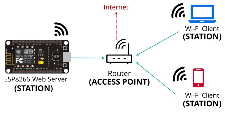
En este modo el ESP se conecta a una red WiFi que ya existe, soporta autenticación a través de WEP, WPA2 y redes abiertas (sin password). La conexión a redes WPA2 enterprise (como Eduroam) es posible, sin embargo, su configuración es muy compleja.
Con este ejemplo podemos probar a conectarnos a una red WiFi y obtener una dirección IP automáticamente a través de DHCP. Recuerda cambiar el ssid y el password
#include <Arduino.h>
#include <ESP8266WiFi.h>

void setup() {

  Serial.begin(115200);
  WiFi.begin("ssid", "password");  // Replace your ssid and password

  while (WiFi.status() != WL_CONNECTED) {
    Serial.println("Wifi connecting...");
    delay(500);
  }
  Serial.println("Wifi connected");
  Serial.print("IP Address: ");
  Serial.println(WiFi.localIP());
}

void loop() {
  // put your main code here, to run repeatedly:
}
Ejemplo de como configurar multiples redes WiFi
/*
    This sketch shows how to use multiple WiFi networks.

    - Fast connect to previous WiFi network at startup
    - Registering multiple networks (at least 1)
    - Connect to WiFi with strongest signal (RSSI)
    - Fall back to connect to next WiFi when a connection failed or lost
    - Fall back to connect to hidden SSID's which are not reported by WiFi scan

    To enable debugging output, select in the Arduino iDE:
    - Tools | Debug Port: Serial
    - Tools | Debug Level: WiFi
*/

#include <ESP8266WiFiMulti.h>

ESP8266WiFiMulti wifiMulti;

// WiFi connect timeout per AP. Increase when connecting takes longer.
const uint32_t connectTimeoutMs = 5000;

void setup() {
  // Don't save WiFi configuration in flash - optional
  WiFi.persistent(false);

  Serial.begin(115200);
  Serial.println("\nESP8266 Multi WiFi example");

  // Set WiFi to station mode
  WiFi.mode(WIFI_STA);

  // Register multi WiFi networks
  wifiMulti.addAP("ssid_from_AP_1", "your_password_for_AP_1");
  wifiMulti.addAP("ssid_from_AP_2", "your_password_for_AP_2");
  wifiMulti.addAP("ssid_from_AP_3", "your_password_for_AP_3");
  // More is possible
}

void loop() {
  // Maintain WiFi connection
  if (wifiMulti.run(connectTimeoutMs) == WL_CONNECTED) {
    Serial.print("WiFi connected: ");
    Serial.print(WiFi.SSID());
    Serial.print(" ");
    Serial.println(WiFi.localIP());
  } else {
    Serial.println("WiFi not connected!");
  }

  delay(1000);
}
📖 Este ejemplo fue tomado del repositorio de Arduino de la comunidad de ESP8266.
Access Point mode
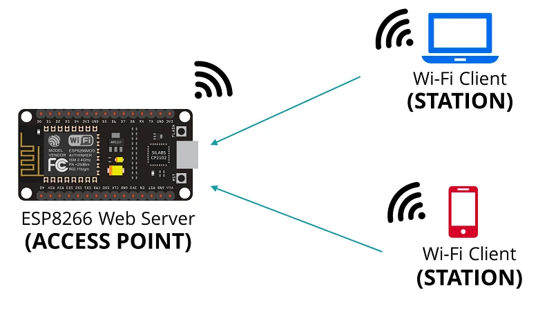
El modo softAP nos permite crear nuestro propio Access Point, y asignar direcciones IP a los clientes que se conectan a él (máximo 8). Este modo es muy útil para permitir la configuración de un WiFi externo a través de una interface web como se explicará en la sección de Captive portal.
#include <ESP8266WiFi.h>

void setup() {
  delay(1000);
  Serial.begin(115200);
  Serial.println();
  Serial.println("Configuring access point...");  /* You can remove the password parameter if you want the AP to be open. */
  WiFi.softAP("ESPssid", "password");

  IPAddress myIP = WiFi.softAPIP();
  Serial.print("AP IP address: ");
  Serial.println(myIP);
}

void loop() {
  // put your main code here, to run repeatedly:
}
La función softAP acepta parametros opcionales que nos permiten configurar más detalles:
WiFi.softAP(const char* ssid, const char* password, int channel, int ssid_hidden, int max_connection)
- ssid: maximum of 31 characters
- password: minimum of 8 characters. If not specified, the access point will be open (maximum 63 characters)
- channel: Wi-Fi channel number (1-13). Default is 1
- ssid_hidden: if set to true will hide SSID
- max_connection: max simultaneous connected stations, from 0 to 8
Por defecto en AP mode el ESP tendrá la dirección 192.168.4.1
Web server
Con este ejemplo podemos crear un servidor web mínimo:
#include <ESP8266WiFi.h>
#include <ESP8266WebServer.h>

ESP8266WebServer server(80);

void handleRoot() {
  server.send(200, "text/html", "<h1>Hello world!!</h1>");
}

void setup() {
  delay(1000);
  Serial.begin(115200);

  WiFi.begin("ssid", "password");  // Replace your ssid and password

  while (WiFi.status() != WL_CONNECTED) {
    Serial.println("Wifi connecting...");
    delay(500);
  }
  Serial.println("Wifi connected");
  Serial.print("IP Address: ");
  Serial.println(WiFi.localIP());

  server.on("/", handleRoot);
  server.begin();
  Serial.println("HTTP server started");
}

void loop() {
  server.handleClient();
}
Para hacer servidores más complejos y de respuesta rápida puede probar la librería ESPAsyncWebServer
Network Time Protocol - NTP
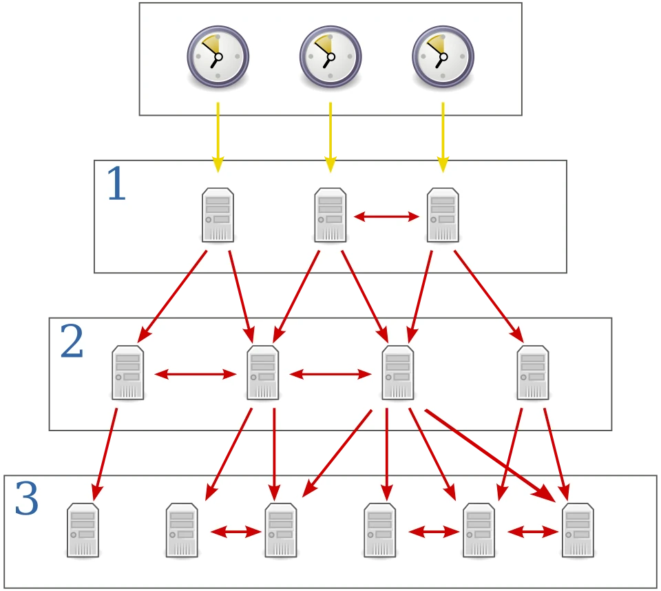
The Network Time Protocol (NTP) is a networking protocol for clock synchronization between computer systems over packet-switched, variable-latency data networks. In operation since before 1985, NTP is one of the oldest Internet protocols in current use. NTP was designed by David L. Mills of the University of Delaware.
NTP is intended to synchronize participating computers to within a few milliseconds of Coordinated Universal Time (UTC).
Podemos utilizar el protocolo NTP para sincronizar el reloj de nuestro ESP y de esta manera poder saber a que hora se tomaron las lecturas de determinado sensor (por ejemplo). Lo podemos hacer desde cero como en este ejemplo o utilizar una librería como NTPclient.
Aquí hay un ejemplo de código mínimo:
#include <NTPClient.h>
#include <ESP8266WiFi.h>
#include <WiFiUdp.h>

WiFiUDP ntpUDP;

// By default 'pool.ntp.org' is used with 60 seconds update interval and no offset
NTPClient timeClient(ntpUDP);

// You can specify the time server pool and the offset, (in seconds)
// additionally you can specify the update interval (in milliseconds).
// NTPClient timeClient(ntpUDP, "europe.pool.ntp.org", 3600, 60000);

void setup(){
  Serial.begin(115200);
  WiFi.begin("ssid", "password");

  while ( WiFi.status() != WL_CONNECTED ) {
    delay ( 500 );
    Serial.print ( "." );
  }

  timeClient.begin();
}

void loop() {
  timeClient.update();
  Serial.println(timeClient.getFormattedTime());
  Serial.println(timeClient.getEpochTime()); // Unix timestamp
  delay(1000);
}
Unix time is a date and time representation widely used in computing. It measures time by the number of non-leap seconds that have elapsed since 00:00:00 UTC on 1 January 1970, the Unix epoch. For example, at midnight on 1 January 2010, Unix time was 1262304000
Una vez tenemos sincronizada la hora podemos utilizar una librería como la Arduino Time Library, para manejar fechas y horas.
Instalar librerías
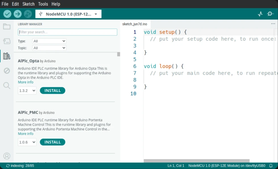
Para instalar librerías abrimos la ventana Arduino library manager (Sketch → Include Library → Manage libraries.) o clickando el botón de la izquierda con un ícono de libros.
Arduino Language Reference
ESP8266 Hoja de datos
ESP8266 tutorial on random nerd tutorials